

In the world of audiovisual (AV) technology, clarity is key. Whether you're building a conference room, live venue, classroom, house of worship, or even a home theater, there’s one essential tool that helps everyone from designers to technicians to end users understand the system’s architecture—the AV Signal Flow Diagram.
Much like a blueprint for an architect or a circuit diagram for an electrical engineer, an AV Signal Flow Diagram lays out the connections between devices, shows how audio and video signals move from one point to another, and illustrates the system’s overall design intent.
For beginners, these diagrams might seem technical or even intimidating at first glance. But once you understand how they work and why they matter, they become a powerful communication and troubleshooting tool. This comprehensive guide will introduce you to the world of AV Signal Flow Diagrams—from the basics to advanced layout strategies—and show you how to read, create, and optimize them.
What Is an AV Signal Flow Diagram?
An AV Signal Flow Diagram is a schematic or graphical representation that illustrates the path audio and video signals take as they move through an AV system. These diagrams use standardized symbols and lines to show sources, processors, displays, speakers, amplifiers, switchers, network connections, and more.
More than just showing which device is connected to what, signal flow diagrams depict how signals move:
From source (e.g., laptop, camera, microphone)
Through processing (e.g., DSPs, switchers, scalers)
To destination (e.g., speakers, projectors, displays)
It’s the visual language of AV design.
Why Are AV Signal Flow Diagrams Important?
A. Clear Communication
Whether you’re working with AV designers, engineers, installers, or clients, the AV Signal Flow Diagram ensures everyone is on the same page. It eliminates ambiguity by clearly showing signal direction, types, and device roles.
B. Installation Guide
For installers and integrators, signal flow diagrams act as a reference during system deployment. Knowing where each cable terminates and how each device connects helps speed up installation and reduce errors.
C. Troubleshooting and Maintenance
A well-documented AV Signal Flow Diagram makes it easier to diagnose issues. If there’s a signal failure, the diagram helps trace the path and pinpoint where the breakdown occurs.
D. Documentation and Compliance
For larger facilities or enterprises, AV signal flow diagrams form part of official documentation, required for compliance, certification, or future expansion.
Key Components of an AV Signal Flow Diagram
Let’s break down the essential elements:
A. Signal Sources
These are devices that generate audio or video signals:
Microphones
Cameras
Laptops
Media players
Wireless receivers
B. Signal Processors
These handle routing, amplification, scaling, or mixing:
AV switchers/matrixes
Audio DSPs
Video scalers
Encoders/decoders
AV-over-IP switches
C. Destinations (Outputs)
Devices that receive and output the signal:
Loudspeakers
Amplifiers
Projectors
Displays
Streaming encoders
D. Connectors and Signal Types
Lines connecting devices usually include a label for the signal type:
HDMI, SDI, VGA (Video)
XLR, TRS, RCA (Audio)
Dante, AVB, AES67 (Networked audio)
HDBaseT, NDI, IP (AV-over-IP)
Each line has an arrow to indicate signal direction.
Understanding Signal Flow: Audio vs Video
A. Audio Signal Flow
Typically begins at a microphone or audio playback device and moves through:
Input stage – Preamp or mixer
Processing – EQ, compression, DSP
Amplification – Power amp
Output – Speaker
A simple AV Signal Flow Diagram for audio might look like:
Mic → Mixer → DSP → Amplifier → Loudspeaker
B. Video Signal Flow
Starts from a camera, computer, or media player and flows through:
Switching – Video matrix
Scaling/Processing – Scalers, encoders
Distribution – AV-over-IP or HDBaseT
Output – Display or projector
For example:
Laptop → HDMI Switcher → Scaler → Projector
How to Read an AV Signal Flow Diagram
At first glance, AV diagrams can look like a spaghetti mess. But understanding a few conventions helps you break them down quickly:
Direction
Arrows show flow. Always follow arrows from input to output.
Device Roles
Boxes or icons represent devices. Labels identify what each device is doing (e.g., “Amplifier,” “Matrix Switch,” “DSP”).
Signal Types
Lines are often color-coded or labeled:
Red/Blue/Black lines – Audio (analog/digital)
Green or Yellow lines – Video
Gray/Dotted lines – Control or network
Signal Conversion
Devices that change signal type (e.g., analog to digital) are often represented with specific symbols or callouts.
Creating Your First AV Signal Flow Diagram: Step-by-Step
If you’re designing a system, here’s how to create a basic AV signal flow diagram:
Step 1: List Your Equipment
Identify:
All sources (mic, PC, camera)
All processors (DSP, switcher, encoder)
All destinations (displays, speakers)
Step 2: Determine Signal Paths
For each source, map out:
Where it goes
What format the signal is in
What processing is needed
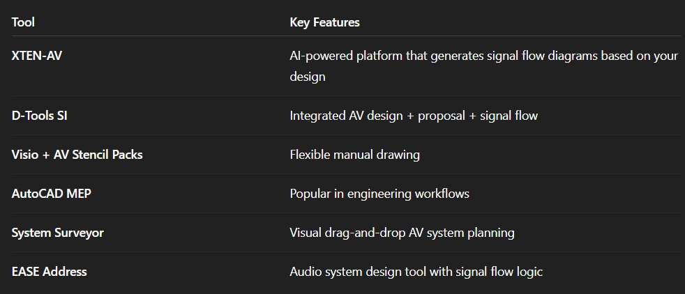
Step 3: Choose Software
Use tools like:
XTEN-AV (which auto-generates AV Signal Flow Diagrams)
Microsoft Visio
Lucidchart
AutoCAD
D-Tools SI
Vectorworks
Step 4: Draw Devices and Connect Them
Use standard shapes or blocks
Connect with arrows showing flow
Label signal types
Step 5: Review for Clarity
Avoid clutter. Group related items (e.g., audio on one side, video on the other). Use legends if necessary.
Examples of AV Signal Flow Diagrams
A. Simple Conference Room
Laptop → HDMI Switcher → Display
Mic → DSP → Amp → Ceiling Speakers
B. Live Event Setup
Wireless Mic → Mixer → DSP → Line Array Speakers
Camera → SDI Matrix → Video Encoder → LED Wall
Video Playback → Scaler → Projector
C. AV-over-IP Classroom
Instructor PC → AV Encoder → Network Switch → AV Decoder → Display
Wireless Mic → Network DSP → Powered Speakers
Advanced Concepts: Layered Signal Flow
In large systems, signal flow can be broken into layers:
Audio Layer
Video Layer
Control Layer
Network Layer
Each layer has its own diagram or is color-coded in a master diagram. For example, Crestron or Q-SYS systems often have control flow alongside AV signal flow, showing where touch panels or automation devices interact.
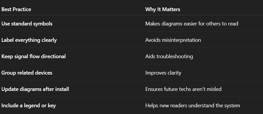
Best Practices for AV Signal Flow Diagrams
AV Signal Flow Diagrams in Modern Design Workflows
With the rise of AI design tools like AI Drawing Generators or platforms that auto-create diagrams based on equipment lists, AV designers can now:
Automatically create AV Signal Flow Diagrams
Generate BOMs and cable schedules in parallel
Simulate system behavior (audio levels, resolution handling)
Integrate signal flow into AV control logic
These AI-enabled features accelerate design, reduce manual work, and improve system accuracy.
AV Signal Flow vs. System Block Diagrams vs. Rack Elevations
Let’s differentiate three common types of AV drawings:
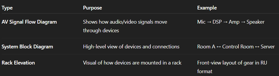
Signal flow diagrams are functional, while others are physical or architectural.
How Beginners Can Learn to Create AV Signal Flow Diagrams
A. Start Small
Practice drawing a basic room:
Laptop to display
Microphone to speaker
B. Use Templates
Many AV software platforms come with templates or drag-and-drop blocks.
C. Watch Tutorials
YouTube, AVIXA training, or integrator workshops are great places to learn.
D. Learn Signal Types
Understanding HDMI, Dante, AES67, HDBaseT, etc., will help you label flows accurately.
Future of AV Signal Flow Diagrams: Smart & AI-Generated
As AV systems become more IP-based and modular, signal flow diagrams will evolve:
Real-time diagrams showing active connections
AI-generated diagrams from voice prompts ("Create a 3-zone audio system")
Interactive signal maps for live events and troubleshooting
Cloud-synced updates across teams and locations
Tools will eventually link signal diagrams to digital twins, maintenance logs, and automated workflows—making AV systems more intelligent and manageable.
Conclusion
An AV Signal Flow Diagram may seem like a technical drawing, but it’s far more than that—it's the lifeline of your AV system design. From planning to installation to troubleshooting, it's the one tool that gives everyone—from designers to technicians to clients—a shared understanding.
If you're just starting in AV, learn how to read and create these diagrams. If you're an experienced professional, invest in better diagramming workflows and tools. Either way, understanding signal flow isn't just helpful—it’s essential.
Mastering the AV Signal Flow Diagram means mastering clarity, control, and confidence in every AV project you touch.